Today we’ll create a resonant filter. Filter design is a complex topic that keeps DSP engineers’ brains busy worldwide, and for now we won’t get too far into that. For not let’s just add a simple resonant Low-Pass, Band-Pass and High-Pass filter to our plugin. We will use an algorithm by Paul Kellett.
Creating the Filter
Let’s start by creating a new C++ class named Filter. Make sure you add it to all targets. In Filter.h, remove the #include <iostream> and add the following class:
class Filter {
public:
    enum FilterMode {
        FILTER_MODE_LOWPASS = 0,
        FILTER_MODE_HIGHPASS,
        FILTER_MODE_BANDPASS,
        kNumFilterModes
    };
    Filter() :
    cutoff(0.99),
    resonance(0.0),
    mode(FILTER_MODE_LOWPASS),
    buf0(0.0),
    buf1(0.0)
    {
        calculateFeedbackAmount();
    };
    double process(double inputValue);
    inline void setCutoff(double newCutoff) { cutoff = newCutoff; calculateFeedbackAmount(); };
    inline void setResonance(double newResonance) { resonance = newResonance; calculateFeedbackAmount(); };
    inline void setFilterMode(FilterMode newMode) { mode = newMode; }
private:
    double cutoff;
    double resonance;
    FilterMode mode;
    double feedbackAmount;
    inline void calculateFeedbackAmount() { feedbackAmount = resonance + resonance/(1.0 - cutoff); }
    double buf0;
    double buf1;
};
In the private section we of course have the values for filter cutoff and resonance. mode indicates what mode (Lowpass, Highpass, Bandpass) the filter is currently in. feedbackAmount, buf0 and buf1 are values used by the filter algorithm (more on this later). The constructor just initializes the members to sensible values and calculates the feedback amount. The process function will be called every sample to filter the incoming signal. Because feedbackAmount depends on both cutoff and resonance, the setters for cutoff and resonance have to call calculateFeedbackAmount after updating the member.
Add the filter algorithm to Filter.cpp:
// By Paul Kellett
// http://www.musicdsp.org/showone.php?id=29

double Filter::process(double inputValue) {
    buf0 += cutoff * (inputValue - buf0);
    buf1 += cutoff * (buf0 - buf1);
    switch (mode) {
        case FILTER_MODE_LOWPASS:
            return buf1;
        case FILTER_MODE_HIGHPASS:
            return inputValue - buf0;
        case FILTER_MODE_BANDPASS:
            return buf0 - buf1;
        default:
            return 0.0;
    }
}
Pretty short, isn’t it? The algorithm is basically two first-order lowpass filters in series. First-order means that for every octave above the cutoff frequency, the amplitude is halved (i.e. the volume is reduced by 6dB). The two lines that calculate buf0 and buf1 are quite similar: Each of them is a first-order lowpass filter. The first line takes in inputValue, whereas the second line takes buf0 (the output of the first filter) instead. So the two filters are in series. Two -6dB/octave filters them in series means a reduction of -12dB per octave. This will become clearer in a moment. You can see in the switch statement that buf1 is the lowpass output. Try returning buf0 instead: You’ll get an attenuation of -6dB per octave (instead of -12dB), so the sound has more highs.
The case FILTER_MODE_HIGHPASS is actually quite intuitive. buf0 is just the low frequencies (of a first-order filter). So if we take the inputValue and subtract the low frequencies, we just keep the high ones. You could also use buf1 here for a steeper cut.
case FILTER_MODE_BANDPASS shows that the bandpass output is buf0 - buf1. As already stated, buf0 has slightly more content right above the cutoff frequency than buf1. If we subtract buf1 from buf0, we keep just that content. So: Subtracting a lowpass output from a lower-order lowpass gives a bandpass output.
Calculating buf1 depends on the previous value of buf1. This kind of feedback means that it’s an Infinite Impulse Response (IIR) Filter. Read this for more information on filter types. We’re not going deeper into filter design here, because I think at this point the math would be a little too much.
Using the Filter
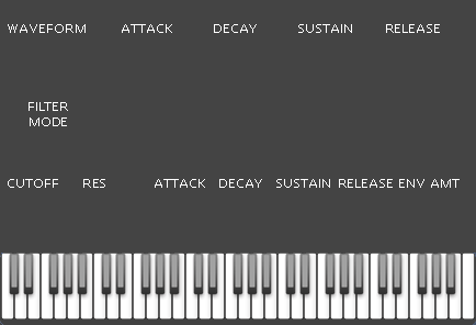
Let’s use our new filter class! We’ll begin with the GUI. Remove bg.png from your project (answer “Move to trash”). Then download the following graphics and add them to the project:
- filtermode.png (Here‘s the TIF)
- knob_small.png (Basically the same knob resized to 50x50 pixels)
- bg.png (A new GUI background with space for the filter controls)
Add the references and IDs to resource.h:
// Unique IDs for each image resource.
#define BG_ID         101
#define WHITE_KEY_ID  102
#define BLACK_KEY_ID  103
#define WAVEFORM_ID   104
#define KNOB_ID       105
#define KNOB_SMALL_ID 106
#define FILTERMODE_ID 107

// Image resource locations for this plug.
#define BG_FN         "resources/img/bg.png"
#define WHITE_KEY_FN  "resources/img/whitekey.png"
#define BLACK_KEY_FN  "resources/img/blackkey.png"
#define WAVEFORM_FN   "resources/img/waveform.png"
#define KNOB_FN       "resources/img/knob.png"
#define KNOB_SMALL_FN "resources/img/knob_small.png"
#define FILTERMODE_FN "resources/img/filtermode.png"
Edit the top of Synthesis.rc to this:
#include "resource.h"

BG_ID       PNG BG_FN
WHITE_KEY_ID       PNG WHITE_KEY_FN
BLACK_KEY_ID       PNG BLACK_KEY_FN
WAVEFORM_ID       PNG WAVEFORM_FN
KNOB_ID       PNG KNOB_FN
KNOB_SMALL_ID       PNG KNOB_SMALL_FN
FILTERMODE_ID       PNG FILTERMODE_FN
In Synthesis.h, #include "Filter.h" and add a private member:
Filter mFilter;
In Synthesis.cpp, update EParams:
enum EParams
{
    mWaveform = 0,
    mAttack,
    mDecay,
    mSustain,
    mRelease,
    mFilterMode,
    mFilterCutoff,
    mFilterResonance,
    mFilterAttack,
    mFilterDecay,
    mFilterSustain,
    mFilterRelease,
    mFilterEnvelopeAmount,
    kNumParams
};
Change the y coordinate for the waveform switch (it’s in the constructor):
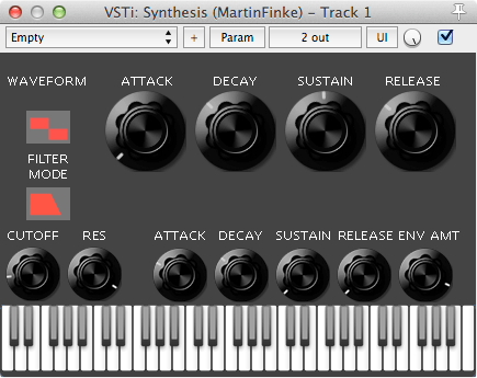
pGraphics->AttachControl(new ISwitchControl(this, 24, 38, mWaveform, &waveformBitmap));
The volume envelope knobs can stay where they are. Let’s add the switch to change filter mode (Lowpass, Highpass, Bandpass). Right above AttachGraphics(pGraphics), add this:
GetParam(mFilterMode)->InitEnum("Filter Mode", Filter::FILTER_MODE_LOWPASS, Filter::kNumFilterModes);
IBitmap filtermodeBitmap = pGraphics->LoadIBitmap(FILTERMODE_ID, FILTERMODE_FN, 3);
pGraphics->AttachControl(new ISwitchControl(this, 24, 123, mFilterMode, &filtermodeBitmap));
We also need a knob to change the cutoff frequency and one for the resonance. We’ll use our new knob_small.png. Add the following code right before the AttachGraphics call:
// Knobs for filter cutoff and resonance
IBitmap smallKnobBitmap = pGraphics->LoadIBitmap(KNOB_SMALL_ID, KNOB_SMALL_FN, 64);
// Cutoff knob:
GetParam(mFilterCutoff)->InitDouble("Cutoff", 0.99, 0.01, 0.99, 0.001);
GetParam(mFilterCutoff)->SetShape(2);
pGraphics->AttachControl(new IKnobMultiControl(this, 5, 177, mFilterCutoff, &smallKnobBitmap));
// Resonance knob:
GetParam(mFilterResonance)->InitDouble("Resonance", 0.01, 0.01, 1.0, 0.001);
pGraphics->AttachControl(new IKnobMultiControl(this, 61, 177, mFilterResonance, &smallKnobBitmap));
Be aware that the value for cutoff should never be 1.0! It will lead to a division by zero inside calculateFeedbackAmount. In ProcessDoubleReplacing, surround the sample generation code with a call to mFilter.process:
leftOutput[i] = rightOutput[i] = mFilter.process(mOscillator.nextSample() * mEnvelopeGenerator.nextSample() * velocity / 127.0);
Finally, we have to react to parameter changes. Add the following cases to the switch statement in Synthesis::OnParamChange:
case mFilterCutoff:
    mFilter.setCutoff(GetParam(paramIdx)->Value());
    break;
case mFilterResonance:
    mFilter.setResonance(GetParam(paramIdx)->Value());
    break;
case mFilterMode:
    mFilter.setFilterMode(static_cast<Filter::FilterMode>(GetParam(paramIdx)->Int()));
    break;
We’re ready to try the filter! Run the plugin, play a few notes and tweak the cutoff.
Resonance
Resonance is basically just a peak at the cutoff frequency. We can realize this by taking a bandpass output, multiplying it by a certain amount and adding it to the signal. Modify the filter’s first line so it looks like this:
buf0 += cutoff * (inputValue - buf0 + feedbackAmount * (buf0 - buf1));
The left part is the same. To the right, we’re just adding (buf0 - buf1) (which is a bandpass output) multiplied by feedbackAmount. You can see from the implementation of calculateFeedbackAmount that feedbackAmount is proportional to resonance. So the peak will be louder if resonance is high.
Run the plugin again. Try tweaking the cutoff knob while holding a note, especially with high resonance. When you turn the resonance all the way up, you’ll get self-oscillation, which can be used to create some interesting sounds. We can get a great variety of sounds with the few parameters we have, especially when we change the filter mode to bandpass or highpass.
From -12dB to -24dB
Instead of just two filters, let’s try putting four of them in series! This will give us an attenuation of -24dB per octave. Add the following two lines right above the switch statement in Filter::process:
buf2 += cutoff * (buf1 - buf2);
buf3 += cutoff * (buf2 - buf3);
This is the same pattern as the buf1 line: Take the output from the previous filter, subtract the last output of this filter, multiply by cutoff and add it to the last output value. You could keep adding lines like this, but it makes the filter more expensive to calculate, and possibly unstable (more on this in a later post). Make sure you modify the switch statement, too:
switch (mode) {
    case FILTER_MODE_LOWPASS:
        return buf3;
    case FILTER_MODE_HIGHPASS:
        return inputValue - buf3;
    case FILTER_MODE_BANDPASS:
        return buf0 - buf3;
    default:
        return 0.0;
}
We’re using buf3 instead of buf1. buf3 is the the output of four first-oder filters in series, i.e. it has an attenuation of -24dB per octave. We haven’t declared (or initialized) buf2 and buf3 yet, so let’s go into Filter.h. Add the private members:
double buf2;
double buf3;
And initialize them to zero (just like buf0 and buf1):
Filter() :
    // ...
    buf0(0.0),
    buf1(0.0),
    buf2(0.0),
    buf3(0.0)
    // ...
If you run the plugin again, you’ll hear that the filter has become steeper: Frequencies above the cutoff get attenuated more strongly. This is what you often find in classic analogue synths.
Now what if we could change the filter cutoff over time?
Filter Envelope
The fun has just begun! Thanks to how we built the EnvelopeGenerator class, it’s very easy to add a second envelope which will modulate the filter cutoff. Actually, we shouldn’t let the envelope change our filter’s cutoff variable directly. That variable is linked to the knob in our GUI. Instead, we’ll add another variable cutoffMod, that will be modified by the envelope. It will be added to the cutoff variable to yield the calculated cutoff. In Filter.h, #include <cmath> and add a private member variable:
double cutoffMod;
Initialize it:
Filter() :
    cutoff(0.99),
    resonance(0.01),
    cutoffMod(0.0),
    // ...
The calculated cutoff is the sum of cutoff and cutoffMod. But we have to make sure it doesn’t go out of the allowed range. Add the following to the private section:
inline double getCalculatedCutoff() const {
    return fmax(fmin(cutoff + cutoffMod, 0.99), 0.01);
};
Let’s make calculateFeedbackAmount use the calculated cutoff:
inline void calculateFeedbackAmount() {
    feedbackAmount = resonance + resonance/(1.0 - getCalculatedCutoff());
}
Finally, let’s add the public setter function for cutoffMod. Since feedbackAmount now depends on the calculated cutoff, the setter has to update it as well:
inline void setCutoffMod(double newCutoffMod) {
    cutoffMod = newCutoffMod;
    calculateFeedbackAmount();
}
Of course we have to change the algorithm as well. Open Filter.cpp and change replace the first four lines of Filter::process (where the buf variables are calculated) with the following:
if (inputValue == 0.0) return inputValue;
double calculatedCutoff = getCalculatedCutoff();
buf0 += calculatedCutoff * (inputValue - buf0 + feedbackAmount * (buf0 - buf1));
buf1 += calculatedCutoff * (buf0 - buf1);
buf2 += calculatedCutoff * (buf1 - buf2);
buf3 += calculatedCutoff * (buf2 - buf3);
The first line ensures the filter won’t be busy when the input is silent. Of course, such a check only makes sense when the code that follows it is notably more expensive than the comparison itself. That seems to be the case here. Apart from that, we have just changed the algorithm so it uses the calculated cutoff instead of just cutoff.
Now that our filter is ready to be modulated from outside (by calling setCutoffMod), we’ll make some changes to the Synthesis class: We’ll add a second envelope that will be triggered just like our existing volume envelope. The user will be able to decide how much the filter’s cutoffMod is affected by the envelope: We’ll add a new parameter called filterEnvelopeAmount with values between -1 and +1. Finally, we’ll add GUI controls for everything.
In Synthesis.h, add the following private members:
EnvelopeGenerator mFilterEnvelopeGenerator;
double filterEnvelopeAmount;
We want both envelopes to be triggered according to MIDI note on/off messages. Replace the implementations for onNoteOn and onNoteOff:
inline void onNoteOn(const int noteNumber, const int velocity) {
    mEnvelopeGenerator.enterStage(EnvelopeGenerator::ENVELOPE_STAGE_ATTACK);
    mFilterEnvelopeGenerator.enterStage(EnvelopeGenerator::ENVELOPE_STAGE_ATTACK);
};
inline void onNoteOff(const int noteNumber, const int velocity) {
    mEnvelopeGenerator.enterStage(EnvelopeGenerator::ENVELOPE_STAGE_RELEASE);
    mFilterEnvelopeGenerator.enterStage(EnvelopeGenerator::ENVELOPE_STAGE_RELEASE);
};
This is just like before, except that enterStage is called on both envelopes. In Synthesis.cpp, insert the following line inside ProcessDoubleReplacing, right before the leftOutput[i] line:
mFilter.setCutoffMod(mFilterEnvelopeGenerator.nextSample() * filterEnvelopeAmount);
As you can see, we’re getting the nextSample from the filter envelope, multiply it by the filterEnvelopeAmount and set the filter’s cutoffMod with the result. We shouldn’t forget to initialize filterEnvelopeAmount. Add the initializer to the constructor:
Synthesis::Synthesis(IPlugInstanceInfo instanceInfo) : IPLUG_CTOR(kNumParams, kNumPrograms, instanceInfo),
    lastVirtualKeyboardNoteNumber(virtualKeyboardMinimumNoteNumber - 1),
    filterEnvelopeAmount(0.0) {
    // ...
}
And let’s not forget to set the filter envelope’s sample rate when it’s changed in our plugin. Add this to Synthesis::Reset:
mFilterEnvelopeGenerator.setSampleRate(GetSampleRate());
We have already added the parameters to EParams, so we just have to initialize them and add knobs. Inside the constructor, just above the AttachGraphics call, add the following:
// Knobs for filter envelope
// Attack knob
GetParam(mFilterAttack)->InitDouble("Filter Env Attack", 0.01, 0.01, 10.0, 0.001);
GetParam(mFilterAttack)->SetShape(3);
pGraphics->AttachControl(new IKnobMultiControl(this, 139, 178, mFilterAttack, &smallKnobBitmap));
// Decay knob:
GetParam(mFilterDecay)->InitDouble("Filter Env Decay", 0.5, 0.01, 15.0, 0.001);
GetParam(mFilterDecay)->SetShape(3);
pGraphics->AttachControl(new IKnobMultiControl(this, 195, 178, mFilterDecay, &smallKnobBitmap));
// Sustain knob:
GetParam(mFilterSustain)->InitDouble("Filter Env Sustain", 0.1, 0.001, 1.0, 0.001);
GetParam(mFilterSustain)->SetShape(2);
pGraphics->AttachControl(new IKnobMultiControl(this, 251, 178, mFilterSustain, &smallKnobBitmap));
// Release knob:
GetParam(mFilterRelease)->InitDouble("Filter Env Release", 1.0, 0.001, 15.0, 0.001);
GetParam(mFilterRelease)->SetShape(3);
pGraphics->AttachControl(new IKnobMultiControl(this, 307, 178, mFilterRelease, &smallKnobBitmap));

// Filter envelope amount knob:
GetParam(mFilterEnvelopeAmount)->InitDouble("Filter Env Amount", 0.0, -1.0, 1.0, 0.001);
pGraphics->AttachControl(new IKnobMultiControl(this, 363, 178, mFilterEnvelopeAmount, &smallKnobBitmap));
This is very similar to the volume envelope knobs, except that we use the smallKnobBitmap here. In addition to the four envelope controls, we also add a knob for the filter envelope amount. The only thing left is to react to user input on these knobs. Add these cases to the switch in Synthesis::OnParamChange:
case mFilterAttack:
    mFilterEnvelopeGenerator.setStageValue(EnvelopeGenerator::ENVELOPE_STAGE_ATTACK, GetParam(paramIdx)->Value());
    break;
case mFilterDecay:
    mFilterEnvelopeGenerator.setStageValue(EnvelopeGenerator::ENVELOPE_STAGE_DECAY, GetParam(paramIdx)->Value());
    break;
case mFilterSustain:
    mFilterEnvelopeGenerator.setStageValue(EnvelopeGenerator::ENVELOPE_STAGE_SUSTAIN, GetParam(paramIdx)->Value());
    break;
case mFilterRelease:
    mFilterEnvelopeGenerator.setStageValue(EnvelopeGenerator::ENVELOPE_STAGE_RELEASE, GetParam(paramIdx)->Value());
    break;
case mFilterEnvelopeAmount:
    filterEnvelopeAmount = GetParam(paramIdx)->Value();
    break;
I Love Acid!
And it’s done! Run the plugin again and modulate the filter using the new envelope! Try the following knob positions and play low notes (around C1) for a particularly squelchy bass sound:
With little work, we have re-used our EnvelopeGenerator class as a filter envelope. This makes our plugin even more flexible, and it’s already capable of a wide range of sounds. We have almost finished a classic monophonic synthesizer! You can download the source files for this post here. In the next post we’ll learn how to create an LFO!